Physicalising LOOT’s Logo
My brother and my dad spent some of their free time last year putting together a CNC router, and they finally got it working over the Christmas holidays. When I was asked to help convert some bitmap images into SVGs so that they could be cut out, I had the idea of cutting out LOOT’s logo, which I’d recently redesigned and redrawn as an SVG. My dad and I got it done late last night / early this morning, so I thought I’d post something to explain what we did and show off some pictures!
As a very brief overview, the CNC router is a drill mounted above a cutting table that can be moved along the x, y and z axes. It’s controlled via a parallel printer port and some circuitry by an old desktop computer running LinuxCNC 2.6. It’s like a 3D printer, but it cuts shapes out of various materials instead of pasting them together (although I think ours could also do rudimentary 3D printing if we had a hot plate).
 Our CNC router, just after cutting some aluminium.
G-coding the Logo
Yes, that’s a terrible pun. The CNC router is controlled by the computer using G-code, and so any shape that is to be cut needs to be converted into a list of G-code instructions to move the drill in that shape. SVG files are a good starting point for converting images because they’re Scalable Vector Graphics, ie. their content is described by coordinates, lines and shapes, rather than what colour all the image’s pixels are, as bitmap formats like JPEG and PNG do. That means they’re already halfway to G-code.
The first step was to remove all the parts of the logo that didn’t describe the logo’s shapes, ie. shadows, shading and tinting. Once that was done, the image was opened in Inkscape and its Path Union and Path Difference tools were used to split the logo into three files, each holding a different layer of the physical logo (from top to bottom: the lettering, the banding and the background).
We then imported the three files into the online conversion tool MakerCAM, which we used simply because it was the first tool my brother found, and used it to set the various machine parameters, such as:
- Drill bit diameter (5 mm)
- Layer depths (3 mm, 6 mm and 12 mm)
- Path overlap (40%)
There were others, but I didn’t make a note of them (I wasn’t paying a lot of attention…). We decided to cut everything out from a single block of wood, rather than cut three separate pieces and glue them together, which is why different layer depths were needed.
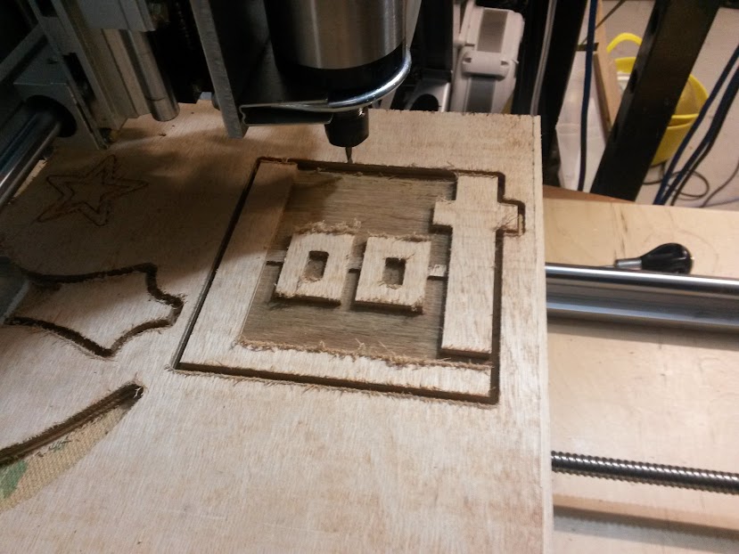
We also added a rectangle cut that extended the interior top edges of the ‘L’ and the ‘t’ beyond the logo edge, and did the same for their interior right edges, so that those corners wouldn’t be rounded. Interior 90° corners get rounded because the drill needs to change direction on a point, and the drill is round, whereas exterior corners can be rotated around (cutting further into the surrounding material) to give a nice point.
When we were happy we hadn’t forgotten anything, we exported the G-code from MakerCAM and transferred the file to the controller computer (which doesn’t have a network connection, so we couldn’t do everything there).
The Hands-On Bit
After finding a bit of 12 mm plywood to experiment with, we secured it to our cutting table by drilling some holes and screwing it down onto the chipboard backing (which is replaceable, clamps would otherwise be a better idea).
Loading the G-code, we saw that it was offset from the cutting area, so we had to enter in manual X and Y axis offsets to put the logo in the right position. This was an exercise in almost complete guesswork, as the offsets seemed to tie into a random number generator, and we were jumping the logo all over the place. We didn’t read the manual: maybe that would have helped. In our defence though, we put in an offset of 10, saw it go the wrong way, so put in -10, and saw it jump ~6 times the distance in the same direction. If that makes sense to you, you may be a genius, crazy, or both.
Anyway, once the logo was in roughly the right place, we set the drill motor to 1440 RPM, hit the start button, switched on the vacuum cleaner, and watched the machine do its magic. It was quite noisy due to some resonances with all the wood involved, so one thing to improve for the future would be to dampen them.
The idea was that the drill would:
- Descend 3 mm into the wood and cut out the interior spaces to reveal the lettering.
- Descend a futher 3mm into the wood and again, cut out the interior spaces, this time also revealing the banding.
- Raise to the wood’s surface level, then cut the logo’s outline in four 3 mm steps.
It would have been faster to cut the interior at a depth of 6 mm to begin with, then raise to 3 mm to cut out the banding, but that puts more stress on the drill bit, and we haven’t stress-tested the router to find out if it can handle that, so we didn’t take the risk. Four 3 mm steps were used to cut the outline for the same reason.
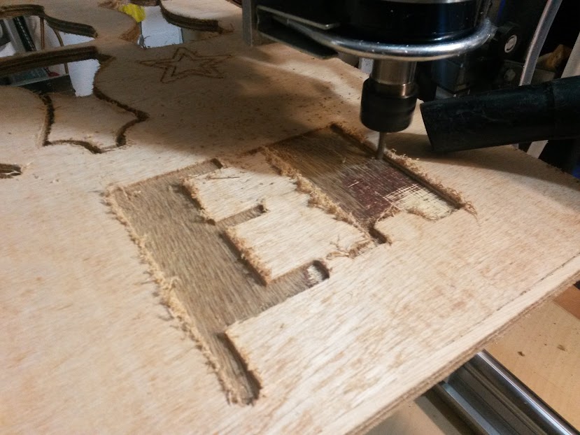 Starting to take shape: so far, so good.
The Best Laid Plans
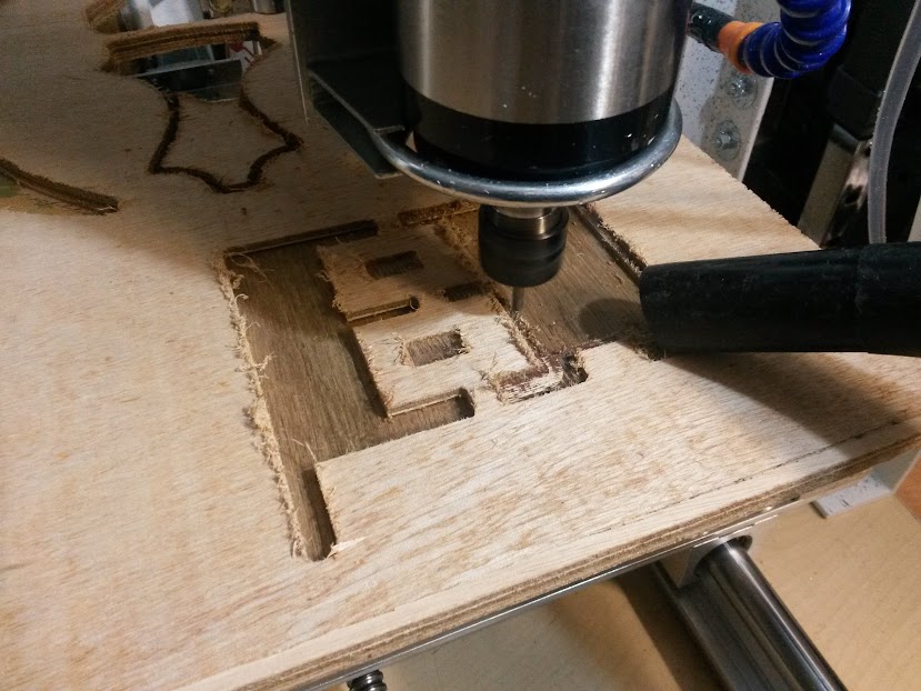 Looking good, but can you spot the problem?
That was the idea, but it turns out we made a few mistakes with the G-code. The first cut (at a depth of 3 mm) didn’t cut over the banding, and neither of the interior cuts included the extended rectangles we’d added. When the drill started to move to cut the outline, we stopped the file execution and tried to figure out what had gone wrong.
It turned out that the extended rectangles had been added at the end of the file, and since G-code is executed line-by-line, that meant they would have been cut last, after the piece was loose (which is obviously not good). Thankfully that was easy enough to sort, as it was possible to run the code from any given line, so we just skipped to the lines at the end of the file.
The banding not being cut over was a bit trickier to solve, as we couldn’t find where the lines for those operations had gone. In the end, we entered in the commands manually, working out the coordinates from the cuts that had passed above and below the bands.
Once those two issues were resolved, we ran the G-code file from where we had stopped it before.
Finishing
1 hour and 40 minutes after we had started cutting, the router was finished its work. There was a lot of what can probably be called sworf along the edges where the drill ran perpendicular to the grain of the top wood layer, and this was removed with a razor blade. The edges and surfaces were then smoothed using 180 grit sandpaper, and a layer of clear matt varnish applied to keep the dirt out.
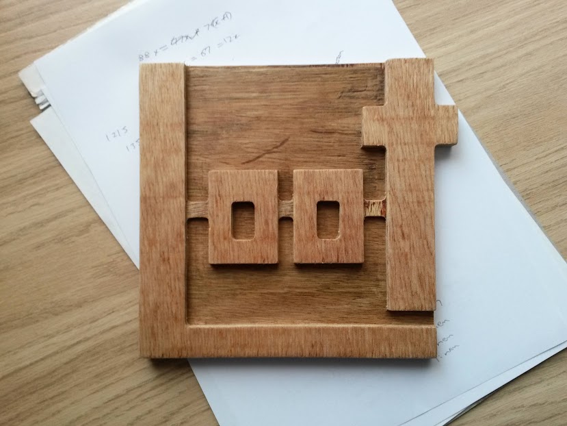 The finished piece. Not bad at all, for a first go.
Possible Improvements
Aside from the G-code problems and the table resonance, there were a few things we think could be done better should we cut another logo out:
- Use a finer-grain plywood to avoid splintering along edges.
- Use our Dremel with a sandpaper tip to do the sanding of corners, as it was difficult to get to them around the ‘O’ lettering.
- Include a switch to a smaller drill bit before cutting the outline, and use it to produce less rounded interior corners.
- Experiment with SVG layering, so that we don’t need to split the image up.
Still, I’m pretty impressed at how successful this was for a first attempt! It wasn’t nearly as fiddly as I thought it might be.
If or when we do get around to a second shot, I’ll upload the working G-code we use to GitHub, just in case there exists another person who wants a physical copy of the LOOT logo and has access to a CNC router.